Savonia article: Design considerations for large scale additive manufacturing, part 1
Before we dive into this article, let’s address the confusion that arises from the different terms used in the world of 3D printing. In simple terms, we’ll be discussing the important design aspects to consider when using robots and extruders for 3D printing. Now, here’s the thing: this technology goes by various names and abbreviations, depending on who you ask and where they come from. Some call it Large Scale Additive Manufacturing (LSAM), others prefer Big Area Additive Manufacturing (BAAM), and there’s also Fused Granulate Fabrication (FGF) thrown into the mix.
But fear not! Despite the jumble of names, they all refer to the same thing: additive manufacturing technology using pellets. Picture this: it involves using a pellet extruder to place materials precisely, and a big gantry system or a robotic arm to move the extruder during the manufacturing process. Think of these systems as the larger and more powerful siblings of those small desktop printers we’re all familiar with.
LSAM at Savonia university of applied sciences
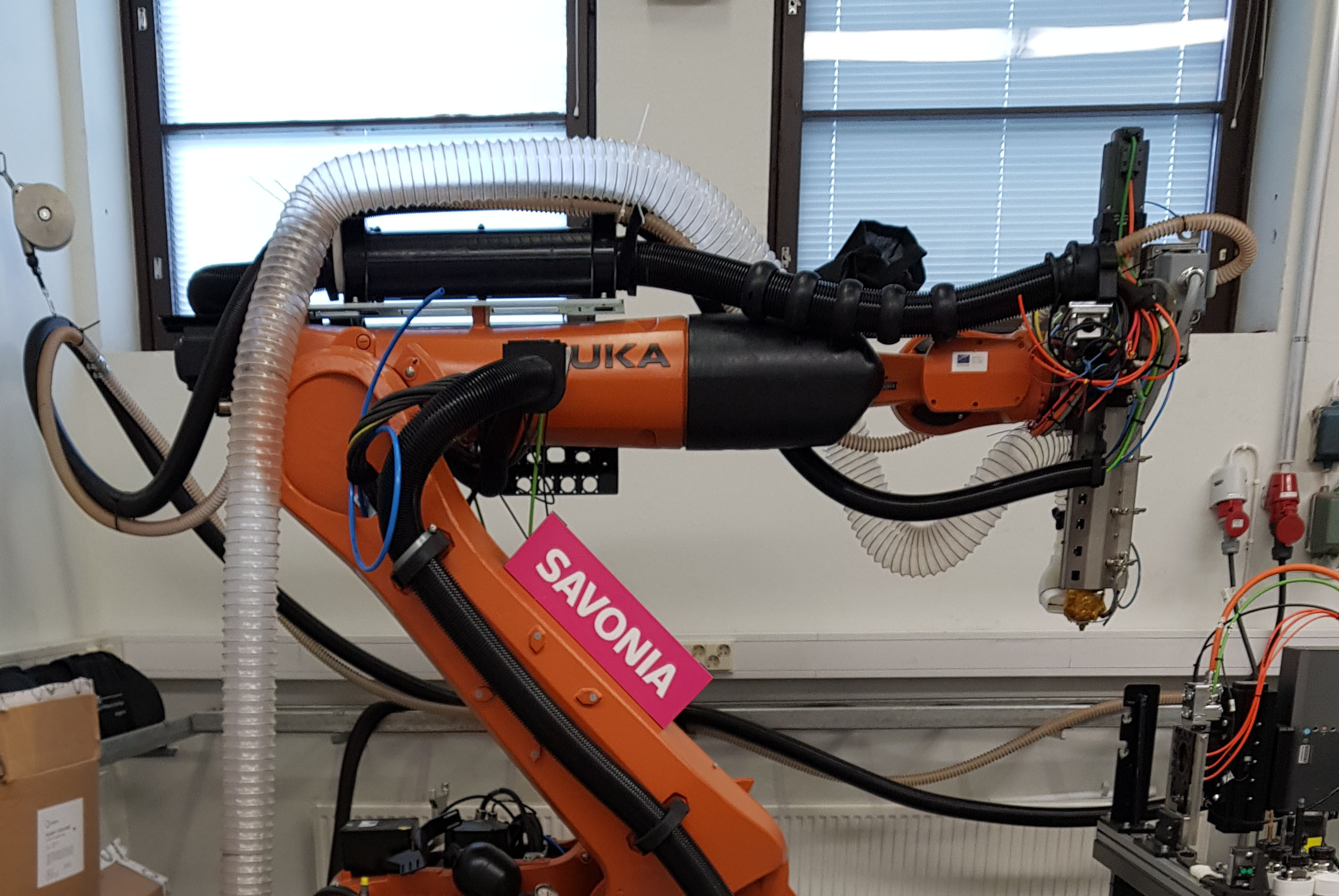
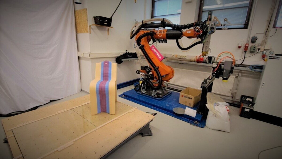
Welcome to the Savonia’s 3DROBO laboratory! In our workshop, we showcase our KUKA robotic arm KR120 2700R with the remarkable CEAD robot extruder, ready to bring our ideas to life. We’ve also acquired two other 3D printing related tools: the Hyperion Robotics concrete extruder and the Flexmill robotic milling toolkit. Although these tools won’t be the focus of this article, they add an extra layer of excitement to our array of capabilities.
Today, we’re excited to share the design considerations we’ve gathered through numerous tests and projects spanning approximately six months of dedicated experimentation. As we delve into these insights, it’s important to keep in mind that these guidelines are specific to our unique equipment and experiences. Therefore, it’s crucial not to assume that they can be universally applied to all machinery and materials. Regarding materials, most of our tests have utilized UPM Formi 3D20 pellets. However, we have also experimented with different materials, and we will discuss the impact of these changes on the printing process parameters and design considerations.
With that said, we invite you to take a glimpse into our robotic print cell. In figure 1, a visual snapshot captures the essence of our robotic printing and machining system.
Design guidelines For Large Scale Additive Manufacturing (LSAM)
One of the goals of Savonia’s “3D-printing with Robots (3DROBO)” -project was to increase our knowledge and expertise in this technology. To achieve this goal, we extensively researched existing techniques, utilized our team’s engineering problem-solving skills, and both adapted existing solutions and developed new ones to ensure the system’s functionality. Our approach drew inspiration from literature as well as our own creative thinking and improvisation. This collection showcases some of the design and manufacturing knowledge we acquired from various sources. It is based on the author’s master’s thesis within the group, focusing on the same topic, and presented here as a condensed version of the thesis work. Our findings serve as a valuable starting point for understanding LSAM technology and contribute to the expanding field of large-scale additive manufacturing. The following “LSAM wisdom nuggets” are examples of the robotic 3D Printing knowledge we have accumulated during the last year in 3DROBO -project.
LSAM Wisdom Nugget #1: Overhangs
Let’s start with the basics. If you’ve dabbled a bit in desktop 3D printing, you might have learned that printing walls at angles greater than 45 degrees isn’t usually a good idea. But remember, this is a general rule of thumb and it depends on factors like the material you’re using, the layer height, cooling, and other settings. These same settings play a bigger role when you’re working on a larger scale. So, if I were to offer a rough suggestion, when printing on a larger scale, it’s better to avoid steep wall angles. While I can’t give you an exact number, you’d need to experiment and test, but let’s say you should try to stay below 30 degrees when using a vertical printing approach. However – depending on the material and print parameters such as the layer height and width, the overhang angle can be larger than that. We’ll dive into different strategies in more detail later on.
LSAM Wisdom Nugget #2: Continuous toolpath
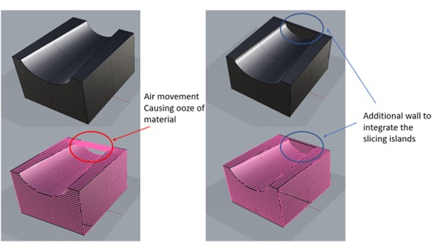
As we’ve discussed before, a notable aspect of FGF is the challenge of halting extrusion, especially with less viscous materials and larger nozzles. These nozzles tend to be quite substantial, and the design of the system doesn’t allow you to reverse the material flow easily. Due to the pressure in the nozzle and the amount of molten material behind the nozzle, the molten material will leak out even during short pauses, for example when printhead movement direction is changed or when extrusion is stopped for air movement. This issue can cause gaps and blobs in the printed walls’ seams and negatively affects surface quality. While there are some techniques like using wiping movements or controlling the extrusion at the start and stop points of the print, our testing has shown that, as a general guideline, it’s better to minimize the use of segmented toolpaths in a single layer – often referred to as “islands” – within the design. If this can’t be avoided, it’s crucial to keep any air movement as brief as possible. In the next wisdom nugget, we will introduce one way that we have successfully practiced for connecting the islands.
LSAM Wisdom Nugget #3: Connecting islands
So, what if our design makes it unavoidable to have these islands? There’s a solution: we can connect them using a double wall integrated into the design. This double wall should be roughly twice the width of the printing path. The concept is that this bridge-like structure will eventually be taken off or machined away after the printing is finished. While this approach ensures better continuity in the print, it does require a bit more material. You can get a clearer idea from the figure 2 that illustrates this concept.
LSAM Wisdom Nugget #4: Nozzle size, layer height and layer width
The very name says it all: large scale. Here, we’re working with hefty nozzles and achieving impressively high deposition rates. To put things into perspective, consider regular desktop printers that usually sport nozzle sizes ranging from 0.2 mm to a maximum of 2 mm. Going beyond 0.8 mm for these printers seems quite unusual. Moreover, their extrusion rates typically stay under 300 grams per hour. However, in the realm of Fused Granulate Fabrication (FGF), we’re setting our starting point even higher than the upper limit of desktop printers. Our nozzles span from 3 mm all the way to 10 mm, in various sizes. The CEAD extruder fitted in the Savonia’s KUKA robot can even reach a 12 kg/h under optimal conditions. So, we’re essentially dealing with a river of molten plastics and plastic composites (figuratively speaking), a flow that we need to physically and thermally effectively control.
Speaking of controlling molten material, conventional wisdom for small-scale desktop printers suggests that the layer width should range from 50% to 200% of the nozzle size. However, our experimentation in the large-scale printing led us to question this ratio’s applicability. Instead, we found that for larger-scale printing, a more suitable range for layer width falls within 120% to 180% of the nozzle size. Interestingly, we discovered that deviating from this range could lead to textural issues on the print surface. A narrower layer width could result in a rough, stretched shark-skin texture, while exceeding 180% of the nozzle size might yield a bumpy texture due to the uneven nature of the extruded bead. This phenomenon hinges on various factors like material traits, print temperature, speed, nozzle shape, and layer height, among others. Surprisingly, the “stretching” or pulling of the material played a significant with this material. This led us to a valuable design guideline: stick to a layer width ranging from 120% to 180% of the nozzle’s diameter. Our usual approach involves first deciding on the desired layer width, and then selecting a nozzle that fits within this ratio. For instance, if we intend to print a 10 mm wide wall, we opt for an 8 mm or 6 mm nozzle.
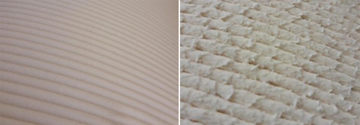
In the image below, you’ll find a comparative test where we’ve printed a 10 mm single wall using both a 10 mm nozzle and a 6 mm nozzle with 3 mm layer height. Can you figure out which nozzle corresponds to each picture? Again, that this is an intuition that we learned from our tests with UPM Formi 3D20 with is wood-plastic composite. The behaviour of other material will be different which we will discuss later.
The same principle applies to layer height, although the ratio of layer height to nozzle size differs between desktop printers and LSAM systems. Let’s bypass references to desktop printers and jump straight into the layer height that we’ve found to be a general guideline for our system. It is important to keep in mind that the behaviour described in this wisdom nugget is most likely very material specific, in this case UPM Formi 3D20. We’ve observed the following:
- Layer heights below 1 mm tend to result in poor surface quality, regardless of nozzle size.
- Layer height shouldn’t surpass the nozzle size, especially when printing walls at an angle.
Ideally, the layer height should fall within the range of ¼ to 2/3 of the layer width. Naturally, this varies based on factors like material, other processing settings, geometry, and print strategy. Apologies if this sounds a bit intricate, but to simplify, we tend to print most of our parts within the layer height range of 2 mm to 4 mm nowadays. Here’s a bonus piece of insight: the core idea behind LSAM is to print faster with higher deposition rates. So, which layer height do you think facilitates a faster printing speed?
LSAM Wisdom Nugget #5: Drying
Straight to the point: make sure to dry the material before printing. Naturally, this requirement varies depending on the material type, but for the most cases, if we skip the drying step, it’ll have a negative impact on print quality. The same goes for mechanical properties – if moisture is present, the strength of the material will decrease. (What it is to do with design guideline then? Well, if I say it myself so, designers should know everything! A good designer should be a decent operator!)
LSAM Wisdom Nugget #6: Tolerances of double walls and overlaps
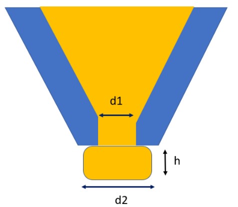
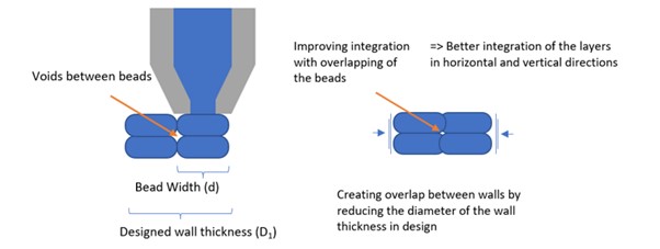
When we’re working on making double walls in different manufacturing processes, we’ve got to think carefully about how we design the walls. This helps make sure that the beads stick together well and that the material stays in the right place when we’re printing. When the beads of material are squeezed out of the nozzle, they often end up looking a bit like ovals. Examining Figure 4, there appear to be gaps between these ovals, resulting in wall porosity and inferior mechanical properties in the print. However, we found that if we make the beads overlap a bit more, these gaps get smaller. This makes the layers of our print stick together better.
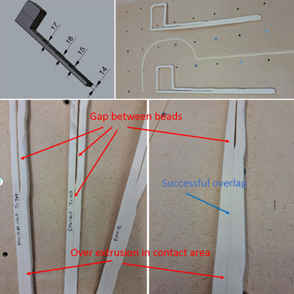
In our experiments, trial and error were employed in creating double walls of various thicknesses while maintaining the nozzle and material extrusion rate unchanged. It was determined that the most favorable outcomes were achieved when the walls were overlapped by 5 to 20 percent. The really good quality prints came out with a 15 percent overlap. This basically means that the shape of the wall should be a little bit smaller – around 5 to 20 percent less – than twice the width of the bead. To do these tests, we used two different nozzles, each squirting out material at different speeds, to create different kinds of double shapes. The test design and observations were illustrated by the figure below.
LSAM Wisdom Nugget #7: Printing Strategies
This golden nugget of insight wraps up this part of our LSAM design exploration, but it’s also the gateway to the exciting possibilities that LSAM holds – something we’ll delve into in upcoming articles. It all begins with the newfound freedom in movement that robots bring to the table. Unlike traditional cartesian printers that can only work in vertical patterns, robots and more advanced CNC systems open our minds to fresh ideas about how parts can be crafted using additive manufacturing. And let me tell you, some of these techniques can be truly game-changing.
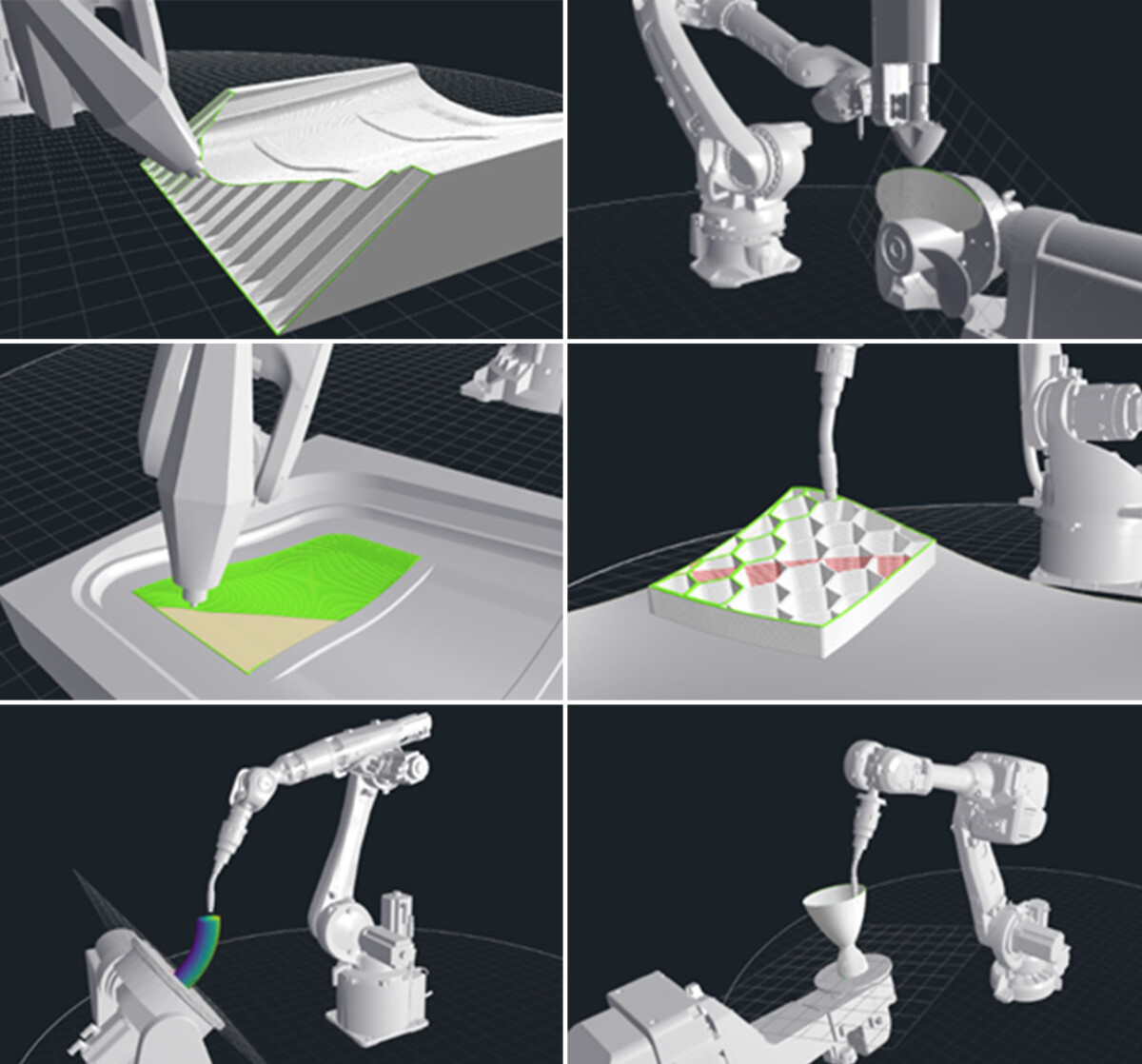
In our current landscape, a software that’s become a staple for most of our printing projects is Adaxis Adaone. This software empowers us with 7 distinct strategies, each with a catchy name: 1- planner printing or vertical printing, 2- angled printing, 3- radial printing, 4- cladding, 5- printing on non-planar surfaces, 6- variable printing orientation, and 7- revolving surfaces. The image below is sourced from their official website and visualizes the concept of broadening our printing path planning approaches. Just take a moment to gaze at these strategies and imagine the impact they could have on your designs. It’s like opening doors of creative possibilities.
When you’re faced with the task of 3D printing a part or starting a design from scratch, the very first step is to carefully examine the shape and figure out the strategy that works best for it, given the movement abilities of your setup. Here’s the catch: each of these strategies comes with its own set of pros, cons, and design factors that designers need to keep in mind. That’s where your role as a designer comes in – understanding at least some of these strategies is essential. While the previous insights focused mainly on vertical printing, it’s worth noting that the design considerations shift slightly for other strategies. In our upcoming articles, we’ll delve deeper into angled slicing and share key insights you should have in your arsenal. Stay tuned!
Alireza Badiee
Testing Engineer
Savonia University of Applied Sciences