Savonia article: Design considerations for large scale additive manufacturing, part 2
In the previous article, we delved into the world of LSAM (Large Scale Additive Manufacturing) and compared its design principles with those of desktop 3D printers. We explored 7 fundamental guidelines, with the last one focusing on printing strategies. Now, let’s pivot our attention to a critical and widely-used printing strategy within LSAM systems – the one known as “angled printing.” In this article, we’ll unpack what angled printing entails and highlight the essential design factors that come into play. To keep things organized, we’ll continue our numbering of the wisdom nuggets from where we left off in the last instalment.
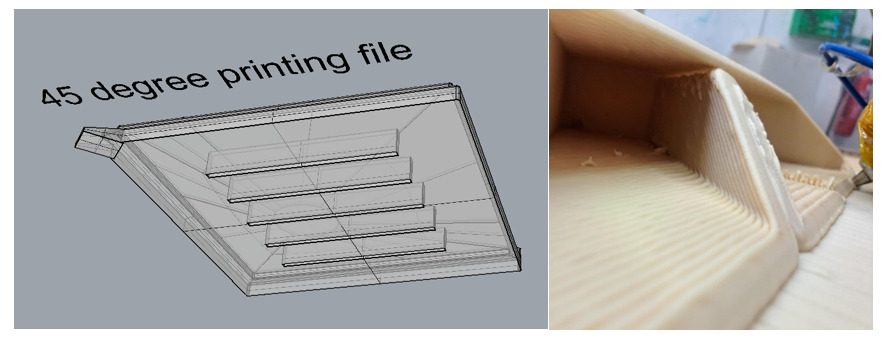
So, what exactly is planner angled printing? Think of it as a close relative to vertical plane printing, but with a unique slicing angle. This strategy holds great value because it reduces or eliminates the amount of support structure for printing overhangs in certain geometries. In various scenarios within LSAM, like mold making and other designs involving roofs, angled slicing proves incredibly useful. How? By reducing the amount of material used, thanks to the decreased requirement for support structures. Moreover, changing the slicing angle can sometimes eliminate the need for segmenting the print or constructing bridges between different parts of the print. Before we go further, let’s take a look at the figure below to visualize the results of printing using the angled slicing technique.
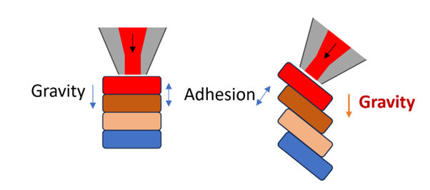
In vertical printing, the adhesion forces and gravity primarily act in the same direction – that’s the parallel to the Z-axis. However, when we venture into angled printing, gravity remains consistent in its orientation, while the adhesion force lines up with the printing direction, perpendicular to the slicing angle. This shift in forces brings about some distinct impacts on the fundamental challenges tied to angled slicing, which we’ll delve into in more detail as we move forward.
LSAM Wisdom Nugget #8 Wall thickness in angled printing and material flow behaviour
Angled printing has truly won our hearts by solving numerous challenges for us. However, it wasn’t an instant victory – understanding the ins and outs of this strategy took quite an effort.
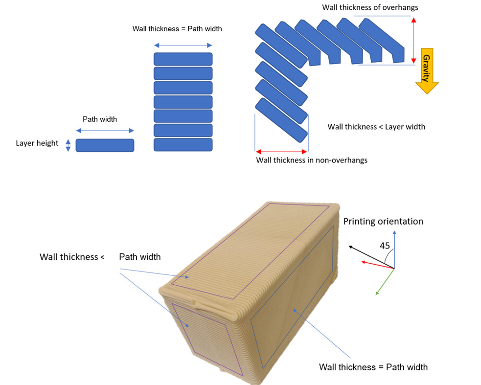
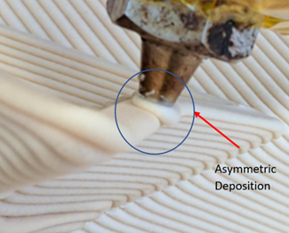
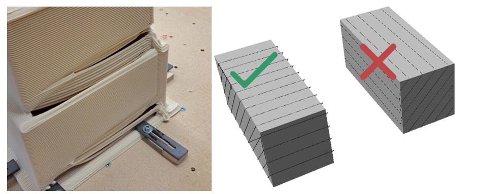
Building on the outcomes of our previous experiments and additional tests, we’ve learned that wall thickness can vary due to the way layers align with each other. This discovery carries significant implications for both design and machining processes, as discrepancies in wall thickness can lead to diverse orientations. Moreover, our scrutiny of material deposition revealed an interesting detail: when it comes to regions like roofs or overhangs, the force of gravity can influence the material’s flow and the way layers are deposited. This, might lead to differences when compared to the intended tolerances. To tackle this, reducing the layer height has shown promise in minimizing these variations, however, with the cost of increase in the printing time. The figure below shows what happens in theory and also what was observed in the practice.
Armed with this knowledge, how can we harness this behavior to our advantage? Well, we can’t exactly change the laws of physics, so gravity remains a constant. However, we can certainly work around it. One way to tackle this issue is identify the areas in our print where this uneven material flow – like on roofs – tends to occur. Then, during the design phase, we make a strategic move by slightly increasing the dimensions in those specific spots. It’s a way to compensate for the effect. Some slicing software also has an option to add the dimensional extension – offsets – that can simplify this process.
Another tactic, as mentioned before, is to reduce the layer height. Smaller layer height helps with the asymmetric extrusion effect, by spreading the path offset between more layers. When the offset is smaller, there is a smaller area where the material can escape through. But, there’s a catch – it also increases the overall printing time. It’s a trade-off, better accuracy at the cost of more time. This approach can be used in some scenarios, depending on the geometry and printing requirements.
There’s yet another approach in the mix, one we haven’t fully explored yet. That’s tweaking the material flow when it comes to printing roofs. This avenue calls for some nifty algorithmic slicing calculations. This could be done in principle, and could be an interesting research project.
For now, armed with the understanding of this behavior, we can consider it a nugget of wisdom to keep in our design toolbox. It’s a guideline that helps us navigate the nuances of angled printing.
LSAM Wisdom Nugget #9 Bridging of the overhangs in angled printing
Angled printing helps us reducing the need for support structures for printing overhangs, but it’s not all plain sailing. If we get back to the discussion on gravity and adhesion forces, there’s a crucial balance to maintain. We need to ensure that the force of adhesion to the previous layer is always stronger than the pull of gravity. If not, gravity takes the lead, and our layers might end up collapsing rather than bonding together. (While other factors like viscosity, nozzle pressure, the shape of the previous layers, and more do play significant roles, this section specifically concentrates on the influence of gravity.)
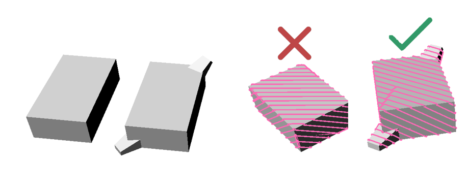
In simple terms, think of a rectangular shape you want to print. To maximize layer adhesion and minimize the risk of overhangs falling, it’s best to slice it along the shorter edge of the rectangle. This combines adhesion with the walls and minimizes the area where overhangs exist. Figure below gives you a clear visual on how to position your part on the printing bed and set the slicing angle just right. It’s like finding the perfect puzzle piece to make your print come together seamlessly.
Another way to tackle this is by adjusting the slicing orientation along two different axes. This approach improves the ability to print edges successfully. However, it’s important to note that employing this technique leads to varied cross-sectional tool paths throughout the printing process, starting from the beginning and continuing until the component is complete. In the next nugget, we will talk about it, and see what problem it will have and what we can do about it.
LSAM Wisdom Nugget #10 Starting and ending ramps for angled slicing
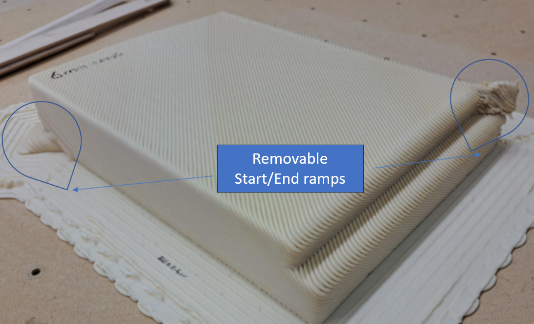
When you’re attempting to slice a component for angled printing along two axes, you might encounter a situation where the distance between tool path’s starting and ending point is short. This means that the layer time is also short at those areas. Unfortunately, this brevity can cause problems, especially with adhesion to the printing platform at the beginning of the print, which might ultimately lead to a failed print (Describing this failure: it’s like initial small deposition path doesn’t stick to the bed, resulting in the formation of a material blob at the outset.). Additionally, due to the material not having enough time to solidify properly at both the beginning and end of the component, there could be issues with deformation.
To overcome this challenge, designers can employ an effective solution of integrating extra ramps within the computer-aided design (CAD) file using Boolean operations, you can ensure a more gradual transition in those critical areas. Once the printing is done, these added ramps can be removed by machining or sawing, leaving you with a successful, well-printed part. Figure below tells it all what we just suggested in principle and in practice.
LSAM Wisdom Nugget #11 Adhesion to the bed and clamping clips
Ensuring proper adhesion to the print bed is fundamental for a successful print. We conducted numerous tests using various bed materials, including glass, aluminum, steel, tape, wood, and Kapton tape, to determine the best option.
Among these materials, UPM Formi adhered acceptably well to a wooden bed without the need for additional glue. We discovered that, within wood-based sheet materials, uncoated medium-density fiberboard (MDF) sheets with a rough surface—often referred to as ‘hard board’—worked exceptionally well for us. However, due to their perforated surface, the bottom surface’s quality may not be perfectly smooth. These sheets typically contain small wood fibers and perforations, providing excellent adhesion.
What’s noteworthy is that these rough MDF sheets simplified the setup process. They eliminated the need for a heated bed or glue, saving valuable print preparation time and cost as they are more budget-friendly than other options.
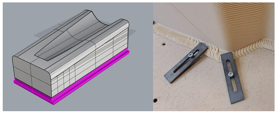
Nevertheless, when we required exceptionally strong adhesion, especially for parts with significant thermal deformation or those destined for later machining, we implemented a design-stage solution. To increase the part stability, we introduced something we call a ‘Raiser’ under the part. This Raiser is an extra piece printed beneath the actual part, mirroring its bottom profile. The Raiser’s lower edge features a specialized ‘Lips’ structure. To secure the Raiser in place on the bed, we used clamps and then printed the actual part on top of it.
Now, when it comes to adhesion, printing on top of something you’ve already printed sticks pretty well, but not as well as the layers sticking to each other. I’d like to highlight that we’re aiming for a specific level of adhesion. Not too weak that things come apart easily, and not too strong that parts can’t be separated without damage. And raiser happen to be good of a solution for us. Figure below shows the raiser in design and practice.
LSAM Wisdom Nugget #12 Custom support structure and clearance tolerances
As discussed earlier, angled slicing and printing are effective for creating overhangs with less need for the support structures. However, when printing large flat (or close to flat) surface areas depending on the material and end usage the surfaces can be weak or too flexible. Furthermore, for structures intended for later milling, vibration control becomes another important consideration, necessitating sturdier structures.
On the other hand, in Large Scale Additive Manufacturing (LSAM), it is preferable for parts to be printed in one continuous path, eliminating the need for extrusion stops. We adopted an approach inspired by the literature to create custom support structures. The method involves altering the geometry so that a series of double layers integrated with the geometry are added to the design. To achieve this, we incorporated grooves on the bottom of the part, positioned just beneath the top surface. When the part is sliced, it’s similar to cutting through it halfway, resulting in a support structure resembling two walls for the roofs. This method provides an efficient way to design custom supports for LSAM parts. Currently, we manually create this type of support structure during the design phase. However, we are exploring ways to further enhance the technique’s efficiency by incorporating algorithms to expedite the design process. Please refer to the image below for a visual representation of this process. We will later discuss its accuracy and effectiveness.
LSAM Wisdom Nugget #13 Layer height in Angled slicing
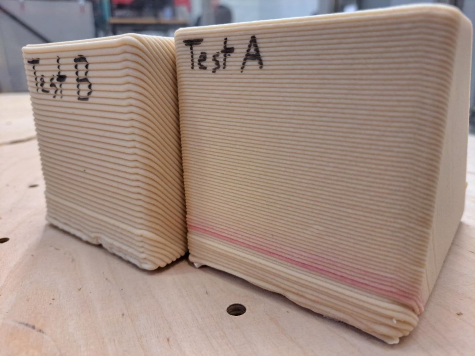
The final tip in this article is centered around layer height when utilizing angled slicing. As we discussed in the previous article, we typically opt for a 2-4 mm layer height in vertical printing. However, in angled slicing, this changes slightly to 1-3 mm. Why the change? Again, it revolves around maintaining a delicate balance between gravity and layer adhesion.
Given the constant conditions of printing (constant printing parameters) less material in each layer, gravity’s pull weakens, while the layer adhesion is the same. This helps prevent material drooping and maintains its shape during the cooling process. To aid in material cooling, we tend to reduce printing speed and increase cooling in angled printing, ensuring the layers remain solid and maintain their shape. However, there is a trade-off; the mechanical strength of the printed parts may slightly decrease.
In conclusion, please refer to the image displaying successful tests of angled prints with 1 and 3 mm layer heights. Stay curious!
Alireza Badiee
Testing Engineer
Savonia University of Applied Sciences