Savonia Article Pro: High presicion GNSS tracking with portable size and budget price equipment
Savonia Article Pro is a collection of multidisciplinary Savonia expertise on various topics.
This work is licensed under CC BY-SA 4.0![]()
![]()
![]()
Traditionally GNSS/RTK technology and commercial equipment have been expensive, quite large, require a separate base station mounted on a tripod or having internet connection to a 3rd party service provider for RTK correction signal. Necessary electronics have been integrated to a larger chassis, such as an excavator, drone, etc.
This article is devoted to the results of experimental testing of GNSS RTK (Global Navigation Satellite System, Real Time Kinematic), the purpose of which is to evaluate the accuracy when used in mobile high-precision tracking systems. Experiments are based on a fixed baseline cross reference comparison.
The operating principle of the technology is to eliminate errors caused by signal propagation from the satellite. This error is calculated at a fixed point (the base station) and then transmitted to other receivers (rovers). Transmission of correction messages (RTCM) is possible through different channels, both directly: a radio link wire, and via the Internet using the NTRIP protocol. [1]
NTRIP defines three roles: server-base station, client-rover, caster-web server. RTK2GO.com is a community driven NTRIP caster that allows you to stream your base station and connect to any public base stations.
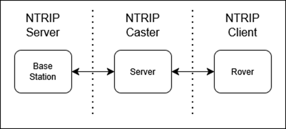
Figure 1. NTRIP Roles Diagram
For evaluation, we chose SimpleRTK2B boards based on u-blox chips. These boards feature modular communications plugins that allow us to test different deployment scenarios using 4G, Wi-Fi, and long- and medium-range radio.
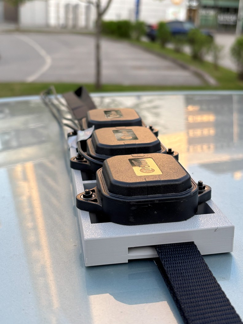
Picture 2. Antennas mounted on rack.
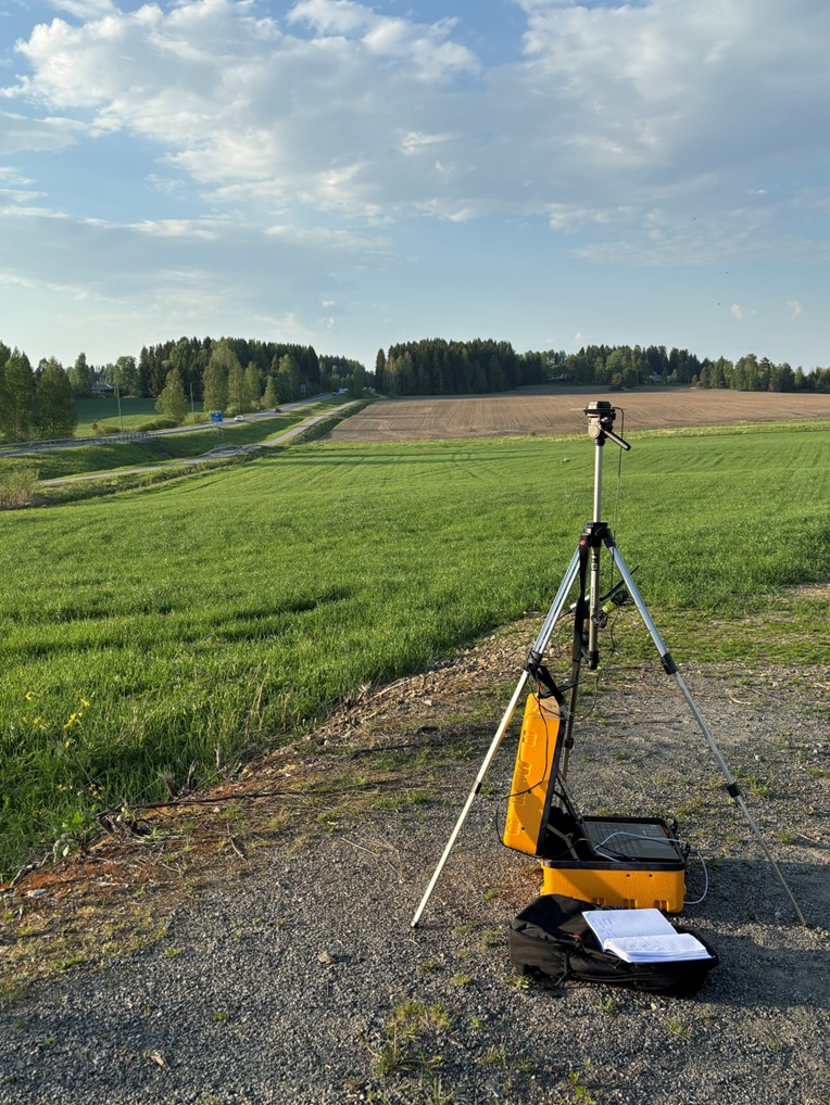
Picture 3. Base Station.
To conduct the experiment, the receiver antennas were mounted on the roof of the car. Since they were always at a fixed distance from each other, the difference between the absolute values of coordinates and speed is an error.
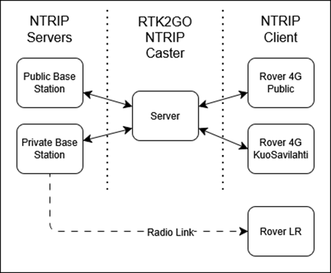
Figure 4. Experiment architecture.
At the same time, three rovers and two Base Stations participated in the experiment: The first receives corrections via Radio Link (RF), the second receives them from the same Base Station, but via internet, the third rover receives them via Internet, but from a publicly accessible Base station. This robust architecture made it possible to compare signal quality depending on different factors: RTCM source and Base Station quality.
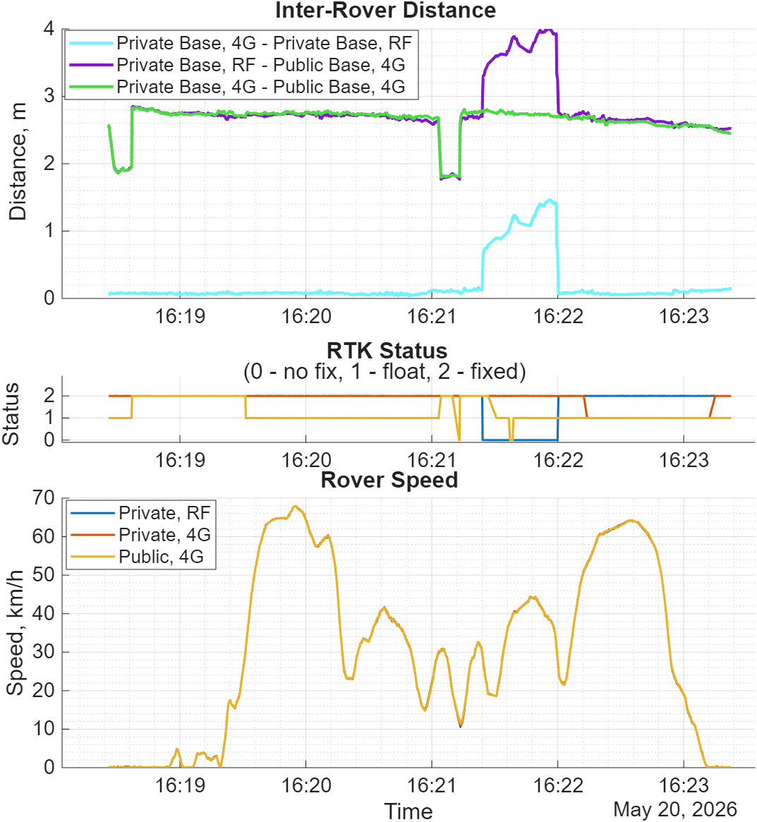
Figure 5. Experimental results. Distance comparison.
We can conclude that:
1) The method of transmitting corrections does not lead to signal degradation
2) The public base station showed some offset, although the distance and speed values are stable.
3) Signals transmitted via the Internet are more robust because they do not require direct line of sight.
The distribution of inter-rover distance and speed, connected to the same base station corresponds to the declared centimeter-level accuracy. Distance between three individual antennas shown in picture 2, is exactly seven centimeters.
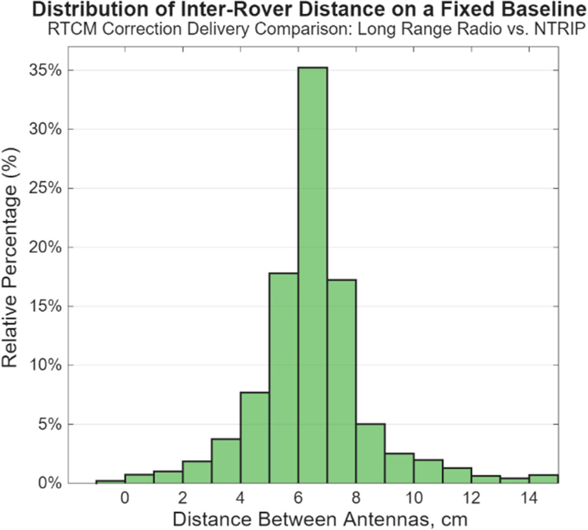
Figure 6. 4G vs RF error distribution for distance measurements.
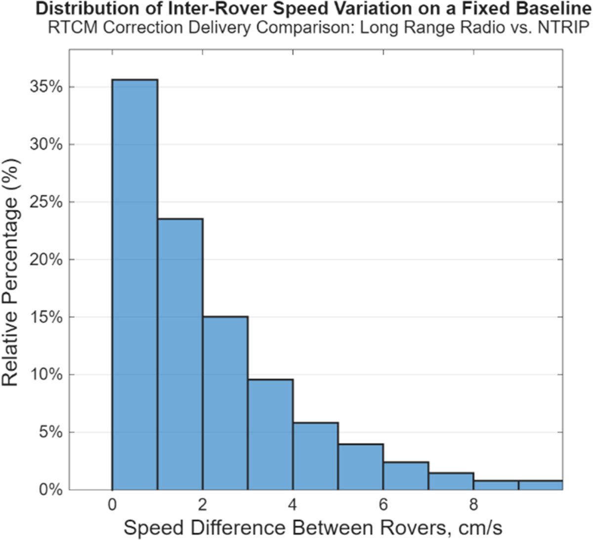
Figure 7. 4G vs RF error distribution for speed measurements.
Conclusion
This experiment has shown that compact and relatively budget boards can provide high performance and centimeter-level accuracy. The size of the antennas and integrated electronics, as well as various communication capabilities, allow the technology to be used on a smaller size enclosure. Both integrated and portable use is viable depending on the application. There are three methods for delivering a correction signal (RTK) to a rover, each with its own characteristics in terms of robustness and availability.
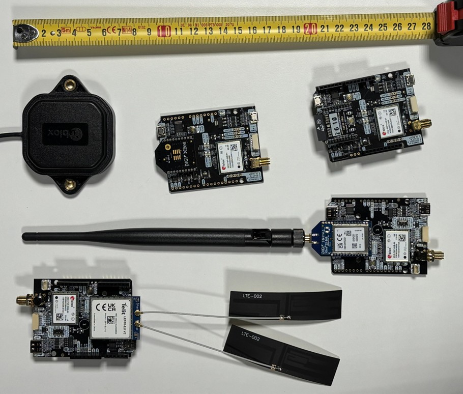
Picture 8. Left to right, up to down. Active GNSS Antenna. Medium Range Radio. Wi-Fi NTRIP Master. Long Range Radio. 4G Cellular Network NTRIP Master. All board’s models are simplertk2B.
This work was carried out in Automaatio ja Tekoäly – Tiedoksi (AuToTIE) project (EAKR / Pohjois-Savon liitto, A80154) in collaboration with PehuTec Oy
References:
What is RTCM | u-blox https://www.u-blox.com/en/technologies/rtcm (11.6.2026)
Authors:
Nikita Toporkov, toporkov.nikita.01@gmail.com
Markku Kellomäki, markku.kellomaki@savonia.fi
Asmo Jakorinne, asmo.jakorinne@savonia.fi
Digicenter, Savonia-ammattikorkeakoulu
Contributors:
Mikhail Toporkov (3d modeling) – mihtop2005@gmail.com, Savon ammattiopisto
Niklas Etling (experiments assistance) – niklas.etling@gmail.com, Savonia-Ammattikorkeakoulu


Authors
Nikita Toporkov, Project Worker, Savonia University of Applied Sciences
Markku Kellomäki, Lecturer, Savonia University of Applied Sciences
Asmo Jakorinne, RDI Specialist, Savonia University of Applied Sciences