Savonia Article: Rapid Prototyping: The Power of 3D Printing and Arduino
#SavoniaAMK
#SavoniaUAS
Abstract:
Many companies face the problem of high engineering costs and long waiting times for projects with the fear of not knowing if the idea will work as thought. Therefore, many companies are implementing more and more Rapid Prototyping. So did we. Rapid Prototyping can allow you to create a physical version of your ideas faster than manufacturing the whole thing with complex milling processes and reduce the detailing level of your part massively. This is why we choose the same path. With the opportunity at Savonia to have eight 3D printers, we created prototypes over prototypes to find the best solutions for our application in nearly no time.
Introduction:
With the power of Savonia’s labs and our tutors’ knowledge, we could create a complete, self-sufficient working system. We were able to develop a Gripping system that can grab any shape and different sizes of objects. This gripping system works as a prototype and should clarify if we can implement such a system in our smart factory shortly.
Migration to the Workflow:
The considerable variation of different part shapes in our smart factory led us to the problem that we had to change the gripping system for every part size and shape. This leads to high maintenance work while operating on our smart factory. Therefore, we created a full-working Gripper that grips nearly any shape without changing the Gripper form itself. This way, we can implement it in our workflow without any maintenance problems. The Current Status of our project is that it only works as a self-sufficient system for demonstration. That’s why we chose Rapid Prototyping. We want to determine if this gripper will work as we want to and lead to optimization and not even more problems.
Road to Gripper – The Project:
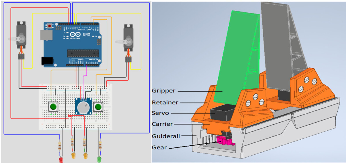
As we started the project work, we only had the idea of improving our system. We sketched out our ideas, combined them with our prework experience, and created multiple ideas for getting them to work within the minimum space used. The whole work contains five main components:
- The Guide rail / The base: We created multiple ideas of how to design the Guide Rails so you can also combine them with the power unit. We sketched as many possibilities as possible and started reviewing them until we got the best fit for our system. After finding the best fit, we Started some detailing in the CAD System. Added Details after Details, did some Test prints to see if the printer’s resolution would allow us to realize it. After several redesigns and Test Prints, we found the correct setup to get an excellent working Rail with implemented Linear gears. With the implemented Linear gears in the base, we have created a solid base that won’t move. Therefore it could be screwed to an industrial Robot arm, for example.
- Carrier with Implemented servo: To let the carrier move on the guide rail, we also added a servo into the carrier. We added a hole to the carrier where you can clip in your servo. After placing the servo, you Assemble the Gear onto it. This way, the servo moves along the Guide Rail with the help of the Gear combination. The carrier also carries the Flexible Grippers itself. Therefore, you must add retainers that will later hold the Flexible grippers on top of the carrier.
- Flexible Grippers: One of the biggest challenges was working with the flexible material and understanding how the gripper works. We tried multiple designs and a massive number of failed prints until we got it to run. The result represents two flexible Grippers made out of TPU with a Hardness of shore 95A. It is made of a flexible material because we want the Grippers to “hug” the object it grabs.
- Electrical conversion: We used a simple design and components for the electric part. We designed it as a self-sufficient system; therefore, we used an Arduino board, two buttons, a potentiometer, a couple of LEDS, and of course, the servo that we built in our carrier. Later, it should be combined with the SPS of the smart factory.
- Program and functionality: We chose the standard Arduino language as a programming language. Based on that, we created a system that can be operated with two buttons, one for opening and one for close. While pressing those, both servos will move toward each other or apart. Furthermore, while pressing a button, the LED of the pressed button will start to blink. You will also find a Potentiometer in between those buttons to define how fast the servo will close and open.
The outcome of the Project:
The outcome of the Project is a tangible product as shown in Figure 2. Also, you can watch the following video link.
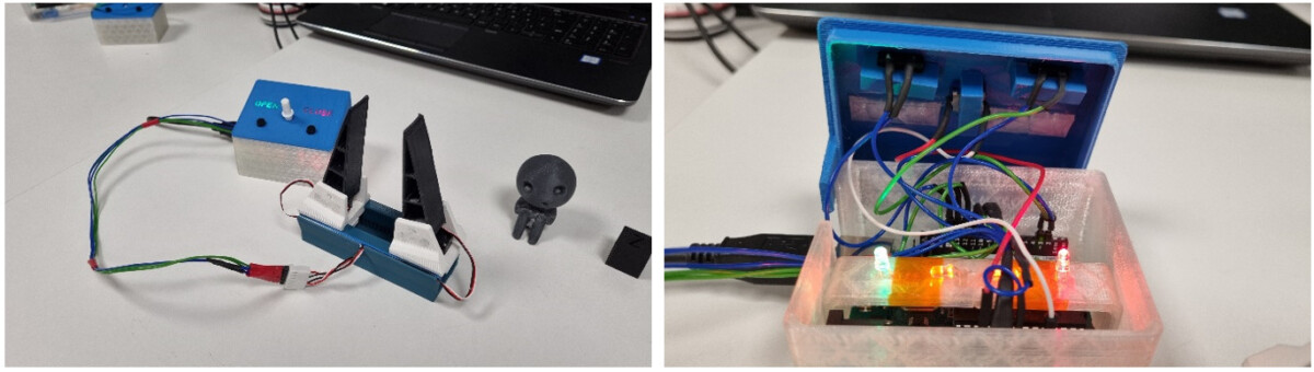
Video Link: 3D Printing and Arduino UNO Prototyping – YouTube
Conclusion:
We created a self-sufficient system that one person can handle. The gripper is made to grab multiple sizes and shapes. Since this is a prototype, you should remember that it might not be as reliable as you wish. One reason is that it’s still all made from plastic without high-grade tolerances, which you would expect if you mill it. For our usage, it was a complete success. We can implement it in our smart factory and understand how it will change the workflow.
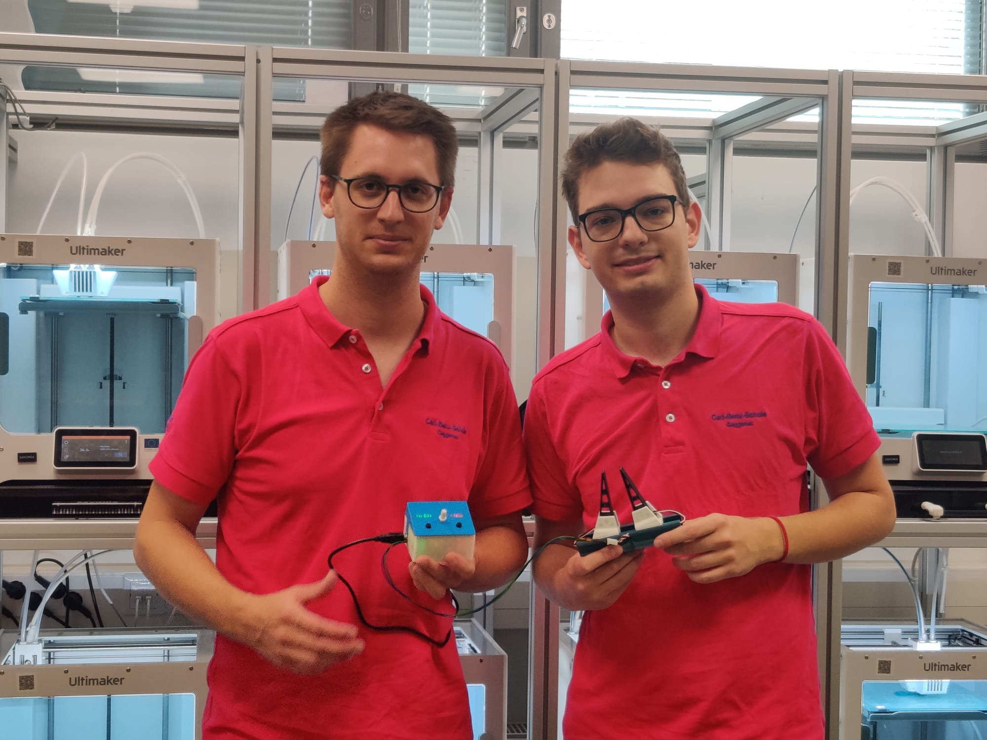
Authors:
Robin Pressl, Max Steinke, Rajeev Kanth
Emails: pressl.robin@gmail.com, steinkemx@googlemail.com, rajeev.kanth@savonia.fi