Abstract:
With the recent developments in smart IoT healthcare applications, the posture of sitting on a chair can be monitored at a regular time interval. In this work, we have demonstrated a prototype that is capable of measuring the time of sitting using four bridge structured load cells and an Arduino Mega microcontroller.
The main goal of this work is to reduce prolonged periods of sitting for better health and productive work conditions. We have studied several pieces of literature that explain how innovative chairs could be developed to monitor the users’ postures. This project’s main focus was to watch time spent in one sitting at the workplace. The load sensors detect weight, and the timer starts to count sitting time, print the sitting time, and alarm the user to take a break in between.
1. Introduction:
Due to the nature of the workplace, people spend more time sitting. This causes risk in metabolic health. Too much sitting means too little physical activity, which leads to a cluster of conditions like high blood pressure, increased blood sugars, and excessive body fat. Taking a 3-5 min break, standing, moving around, or anything else involving physical activity in between will prevent health problems caused by prolonged sitting.
The introduction of ergonomic adjustable chairs has prevented many health problems caused by inappropriate posture with the user. Proper posture could solve the back pain-related risks, but physical inactivity can still cause many problems. Regular breaks in between benefits in many ways. We could spend more time without knowing in one seat and the aim to notify the user with the time of sitting. As a person sits on the chair, the load sensor senses, and the timer turns on. When the person gets up, the timer stops and starts counting again from zero as the sensor senses load.
There were three significant phases in the project, namely 1) An idea development, 2) Design and mechanical build phase, and 3) the programming and testing phase. Each author did extensive brainstorming for its proper design and Implementation in the idea development phase. After concrete formulation of the ideas, the next step planning was done based on the reliability and uniqueness of the project work. We intended to build a simple and easily portable design that can be added to the top surface of an existing chair at the workplace. To hold the loadcells on the wooden frame, we have designed and developed an accurate mask using the 3D printing facilities of Savonia University of Applied Sciences.
Finally, in the programming and testing phase, the code has been written on Arduino IDE and tested accordingly. We have used several components such as Analog to Digital Converters, connecting cables, Arduino Mega Controller, and the wooden frame. The cost of the product is about one hundred euros. Savonia University of Applied Sciences financed all the costs of this work.
2. Related works:
Most design and Implementation on smart chairs [1]-[2] focus on human ergonomics, correcting body posture rather than on prolonged sitting. In recent days, the standing chair has been used as an option for the standard sitting chair. Although standing chairs are a great option, they require different settings and would be hard to work standing for a long time in some situations. In this case, adding some features to the standard chair would be the better option. Many smart chair projects have been done, mainly by notifying the user of the wrong postures. Also, it is possible to get ergonomic chairs at the market manufactured to keep the appropriate body position for human beings.
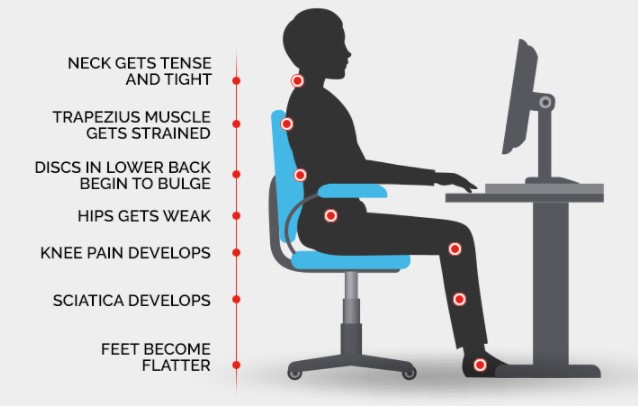
As shown in Fig. 1, it is possible to prevent the pain on joints and risks associated with back pain using the smart chair. Due to workstation designs or other reasons, we could spend more than recommended time sitting. Proper body position while sitting cannot solve risks caused by physical inactivity, reducing some illnesses. Uninterrupted sitting for more than one hour with the recommended body position tends to cause health problems related to body movement. Taking a regular break in between would be the appropriate option in this scenario.
3. Technical Details for the Design and Implementation:
The technical details for the smart IoT chair design and Implementation are divided into three parts, namely 1) Components for building the project and 2) Programming Arduino 3) Realization of the Prototype
3.1 Components for Building the Project:
The equipment used in this project consists of a microcontroller, load cell sensors, amplifier, combinator, jumper wires, and the code. The microcontroller used in this prototype is the Joy-it Mega2560R3 (Joy-IT) [3], which is similar to the Arduino Mega. The project team picked the Mega because it has enough pins, so there will be no problems related to the microcontroller not being compatible later in the project. The Sparkfun (SEN-10245) load cell sensor [4] used in the project can measure a 40-50 kg load (Sparkfun). These sensors need a mount to attach them to the surface. The mount is 3D printed at Savonia’s lab.
A crucial point of the mount is that the inside of the mount is open so that the top surface will press the pressure point of the load cell down. Four of these load cell sensors will be used and mounted on the frame using a Wheatstone bridge for the prototype. SparkFun load cell amplifier Hx711 [5] is an amplifier that makes it able to use a Wheatstone bridge and connect the four sensors to measure small changes in resistance (Sparkfun). Without using a combinator, connecting multiple inputs into the amplifier is impossible. The SparkFun load sensor combinator (BOB-13878 ROHS) [6] can combine four different sensors through 12 wires as input and works perfectly with the amplifier (SparkFun). The Hx711 Arduino library needs to be implemented into the code to make this system work. The library makes it possible to tare the inputs from a zero known start.
The taring starts at startup in the code, and a timer starts running whenever the load is above a certain threshold. In this prototype and testing purpose, the threshold is set to a lower value than it might be once optimized. If the timer is running, it keeps looping and counting the number of milliseconds it is running. It shows this in the console combined with the total load at that specific moment. If the load is below the threshold, the timer switches off and reset. In the first version of the code, the user will only be notified in the console for testing purposes.
3.2 Programming Arduino Microcontroller:
The explanation of the code is given in the following snippet of the Arduino IDE in Fig. 2.
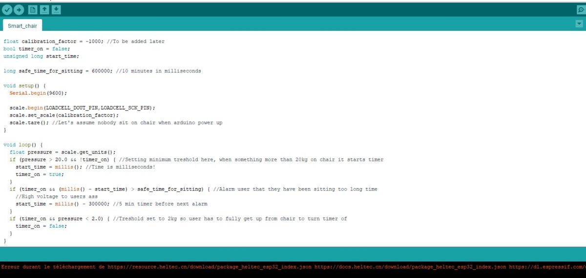
A quick explanation of the code starts with the serial.begin(9600) that is supposed to send data from Arduino to the USB port. In that case, we have two pins where the data will be sent to. Then we have multiple if conditions, the first function is in the case of someone sitting on the chair, for example, after the mass exceeds 20 kg, the timer starts running. Then we have the second function to indicate when someone has been sitting on the chair for a long time. In that case, the user should be notified that is already a time limit. Finally, the last function is that when the user is not on the chair, the timer is not supposed to be on.
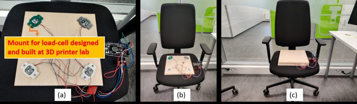
3.3 Realization of the Prototype:
The prototype has been realized as shown in the following Fig. 3.
4. Results and Discussion
Results that have been achieved through the system described in this section can be seen in Fig. 4.
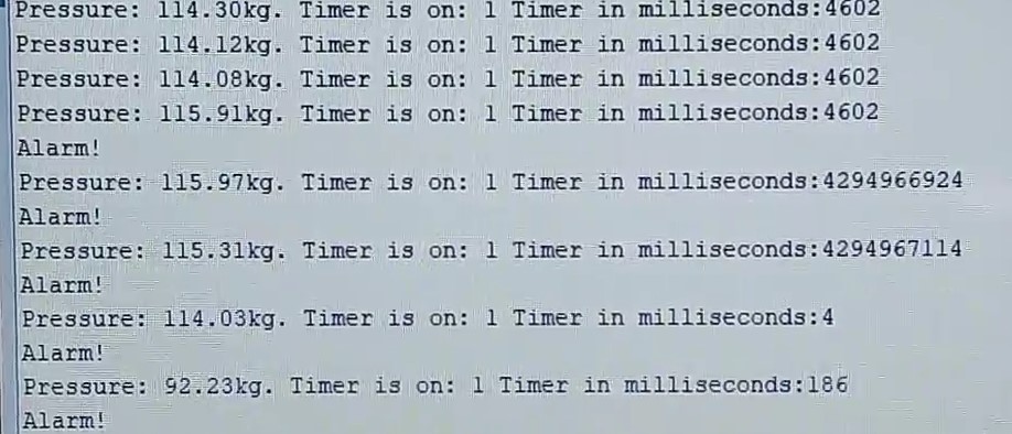
If the user runs the code, the pressure goes to zero, and the timer status and counter will be on zero. Once the pressure, which is in grams and not kilograms as shown in this snapshot, is above the set threshold for a certain amount of time, the “Alarm” will trigger. The timer in milliseconds is when it takes the timer to loop through until the alarm is triggered. There are still modifications necessary in the code to get a better visualization of the output, but the system is working as intended.
The intended outcome for the project was to build a portable surface that can be put at the chair’s surface to help the user be aware of the sitting time and alarm to take a break when anyone passes the recommended time of sitting. The work mentioned above succeeded in notifying the user to take a break and sensing the load in a continuous loop.
5. Tests and Validation
Different kinds of testings were performed throughout the process:
● The first testing was done to check the code’s accuracy, and it was running well at that point, and no bugs were detected.
● The second testing was done to check the functionality of the load sensors, amplifier, combinator, Arduino mega, and connections between wires. Everything was working except one faulty wire connection during the soldering process, but later after some more tests, the results were validated with accuracy.
● The third test was made to check if the timer in the code was working. We also tried to put load and remove the load a couple of times, so the timer starts and turns off, respectively. The timer was working well at this level.
● Some calibration was done to fix the scale unit of the user’s mass.
● The other test was performed to check the program was able to neglect the taring load, detect the desired load, and work with the timer so that when the load is removed, the alarm goes off. At this stage, the program was working as intended.
Future Work
There could be multiple things to be done to optimize the prototype and develop a good end product in the future. One of the improvements could be in the Implementation of the prototype. This includes an opening or manufacturing a chair with the solution built-in, so it doesn’t have to lay on top of a standard chair. This will give a better appearance to the product and make it look more professional. Improvements to the code can be split into two parts: notification and functionality. The notification of the user is not implemented but was intended if enough time was available during this project.
One of the options of notifying the user was through a vibration device mounted into the solution, which would be in the seat of the chair. The slight vibrations like in a standard phone device will nudge the user and tell them that the time is exceeded and it’s time to get up. Another option that could be looked into is a notification on another device such as a phone or a computer.
The product would most likely be used in an office. There will be access to one of these devices in this environment and make it possible to connect the chair to them. The notification could be through an app with an interface that allows the user to set the time manually shorter than the max time limit if desired. Reminders or locking the screen of the computer is another option to force the user to take the break necessary to stay healthy. The prototype’s functionality could be extended if the discussed features are included into consideration. Modifying the time and maybe taking more minor breaks between a long time would be preferred. The current functions and things the prototype displays could be changed to understand better what the product does.
Furthermore, adding more services like detecting bad posture and alerting the user about it. So the chair is multifunctional. Also, the threshold of the user’s mass should be modified to a more logical average adult mass. For example, they are substituting 20kg with 50kg. As the user should get up every 30 minutes an hour, there should be some modifications regarding the previous minimum time set, 10 minutes.
Conclusion
In conclusion, it is possible to design sitting time-reducing mechanisms in chairs using cheap and straightforward electronic materials. It can be built-in into a chair to be connected to a computer or mobile application system. This project cited a simple way of reducing health risks caused by prolonged sitting. The result of the project was successful, and the desired outcome was achieved even though it could be improved in the design and require an end product so the user can easily interact with the device. The project was a meaningful experience where all the members have achieved new skills and learning for future study and ideas for many more projects coming in the future.
Authors:
Timon Padberg, Sojat Sebgaze, Rim Zakar, and Rajeev Kanth
Emails: timon.padberg@edu.savonia.fi, sojat.sebgaze@edu.savonia.fi, rim.zakar@edu.savonia.fi, rajeev.kanth@savonia.fi
References:
[1] M. Park, Y. Song, J. Lee and J. Paek, “Design and Implementation of a smart chair system for IoT,” 2016 International Conference on Information and Communication Technology Convergence (ICTC), 2016, pp. 1200-1203, DOI: 10.1109/ICTC.2016.7763406.
[2] Yusupov, N[odirkhon]; Akhinko, S[ergeii]; Sambath Kumar, R[ohin]; Kumar Singh, H[arish]; Khan, R[ida] & Nikhil, K[ashyap] (2018). Smart Chair: IoT Based Health Telemetry for Air Traffic Controllers and Emergency Response Center Operators, Proceedings of the 29th DAAAM International Symposium, pp.1279-1285, B. Katalinic (Ed.), Published by DAAAM International, ISBN 978-3-902734-20-4, ISSN 1726-9679, Vienna, Austria DOI: 10.2507/29th.daaam.proceedings.184
[3] Joy-IT. (n.d.). Joy-IT Mega2560R3. Joy-IT. Retrieved January 19, 2022, from https://joy-it.net/en/products/ARD-Mega2560R3
[4] Sparkfun. (n.d.). Load Sensor – 50kg (Generic) – SEN-10245. SparkFun Electronics. Retrieved January 19, 2022, from https://www.sparkfun.com/products/10245
[5] Sparkfun. (n.d.). SparkFun Load Cell Amplifier – HX711 – SEN-13879. SparkFun Electronics. Retrieved January 19, 2022, from https://www.sparkfun.com/products/13879
[6] SparkFun. (2017, May 19). SparkFun Load Sensor Combinator – BOB-13878. SparkFun Electronics. Retrieved January 19, 2022, from https://www.sparkfun.com/products/13878