
Savonia Article Pro: IoT Data Collection – Interfacing with Commercial Building Monitoring Solutions, Part I
Savonia Article Pro is a collection of multidisciplinary Savonia expertise on various topics.
This work is licensed under CC BY-SA 4.0![]()
![]()
![]()
Introduction
The ÄLLITÄ project team has been busy figuring out new ways to collect data from Savonia’s campus building in Varkaus. In our previous article on the topic, “Leveraging IoT Solutions for Real-Time Data Acquisition” , we discussed the importance of collecting real estate-related time series data in developing AI-based solutions for energy consumption optimization in public properties. We also investigated some of the data collection systems we had deployed on the site, and how they connect into our existing data backend. In this article we will look into the process of integrating a specific heating energy monitoring device into the data backend for collecting real-time energy consumption data from the Varkaus campus building’s district heating system.
The Device
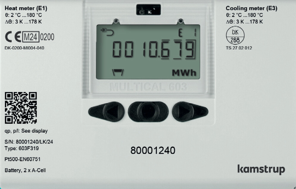
The local district heating company recently installed a new monitoring device into the heat distribution room of the Varkaus campus building. The device is a Kamstrup MULTICAL 603 that can monitor and calculate a wide variety of district heating parameters, such as the temperatures of incoming and outgoing water, the volume, flow, and pressure of water going through the system and the total heating energy used by the building. The device can be equipped with additional communication modules, such as 4G radio, BACnet or NB-IoT, and in this case the device was ordered with a module that allows for reading data over Modbus TCP/IP. The monitoring device can be seen in Figure 1.
The Plan
Integrating this kind of a device into an existing data backend should be a somewhat straightforward process, but since we opted for a rather experimental way of reading the data instead of purchasing something “official”, we did run into a few learning experiences along the way. Much like some of the systems discussed in our earlier article, this set-up also uses a Raspberry Pi 3B for reading data from the Modbus TCP module, and the deployment process was thought out to be as follows:
1. Connect the Modbus TCP module to the Pi’s Ethernet port
2. Connect the Pi to the campus’ IoT network using WLAN
3. Develop and deploy the software and other configurations needed onto the Pi
4. Fire up the software on the Pi and see the data flow.
In practice, the first step involved cutting an Ethernet cable in half and connecting the intact end to the Pi, but only 4 of the wires into the Modbus TCP module since there’s no standard Ethernet / RJ45 connector on the thing (only the green and orange pairs of the cable were used, according to T568B termination). The second step was otherwise simple enough, but the wireless IoT network on the campus needed to be expanded because the signal quality inside the heat distribution room wasn’t good enough for a stable connection.
The Set-Up
Before developing the data collection software on the Pi, the following questions needed to be addressed:
– Does the Modbus TCP module use static IP assignment or DHCP?
– What is the MAC address of the module’s networking interface?
This kind of information should usually be known by the person who ordered the installation of the device, but since the person in question was not available at the moment, the questions were answered on the spot by using tcpdump to listen for possible broadcast DHCP messages (UDP ports 67 and 68) on the Pi’s ethernet interface, to which the Modbus TCP module was now connected. After a short period of listening, DHCP Discover messages from both the Modbus TCP module and the Pi itself could be seen on the wire, and since these messages contain the requesting client’s MAC address, this part of the puzzle was now solved.
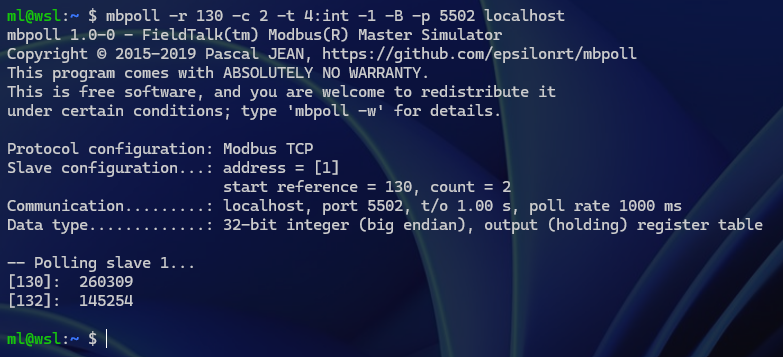
Since it was now also determined that the module does in fact use DHCP, the next thing was to figure out how to give the module an IP address that would stay the same indefinitely. For this purpose, a DHCP server (dnsmasq) was installed on the Pi and configured so that it would provide the Modbus TCP module with a fixed IP address from the same subnet as the Pi based on the module’s MAC address that was captured previously. With all of this in place, the module was confirmed to be working as expected by using a Modbus testing utility for Linux called mbpoll. An example of the output from mbpoll when reading the timestamp registers (130-132 decimal) of the device can be seen in Figure 2.
The Logic
Once all the networking issues were sorted out, the last thing to do was to develop the actual application logic that would periodically read data from the Modbus TCP module and send it to the data backend. Modbus devices generally store data in something called “holding registers”, and most of the development work with these is figuring out what data can be found from which register, what type of data that is and how to read that data correctly.
A single Modbus register has a standard size of 16 bits, which is often insufficient to hold a measurable parameter’s value with enough precision. Common practice in these situations is to combine two 16-bit registers to make a single 32-bit register (or even combine four of these registers for a single 64-bit register, if needed).
The Modbus TCP module in action here has a total of 276 16-bit registers for storing measurement values, unit codes and scaling factors, and getting a single piece of sensible data requires reading all three memory locations for a given parameter. The process outline for getting a single measurement manually would be as follows:
1. Find the value’s memory location and data type from the device’s spec sheet (most values are stored at two different memory locations as two different data types)
2. Read the raw value from that location as either int32, uint32 or IEEE-754 float (measurement values are always 32-bit, big-endian)
3. Find the memory location of the value’s scaling factor from the spec sheet
4. Read the scaling factor from that location as int16 (these are always signed 16-bit)
5. Multiply the raw value with the scaling factor to get the final value
6. Find the memory location of the unit code for that value from the spec sheet
7. Read the unit code from that location as uint16 (these are always unsigned 16-bit, unit code can be one of 33 distinct values)
8. Find the corresponding human-readable unit description from the spec sheet
9. Create a key-value pair of the measurement, e.g. {“PARAMETER_NAME (UNIT)”: VALUE}.
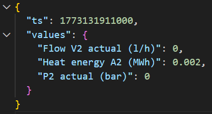
There are 56 measurable parameters in total to which this process needs to be applied. Two of these parameters form the timestamp of the latest set of measurements (there’s a 32-bit value for both date and time, see Figure 2 for an example), and this needs to be converted into a format that the data backend can understand. Finally, the resulting data object consisting of the timestamp and key-value pairs for all parameters needs to be formatted as a JSON string and ultimately sent to the data backend. An example of such a JSON-formatted data object can be seen in Figure 3.
The Application
The app that was crafted to do all of this is a NodeJS program utilizing the “modbus-serial” and “moment” NPM packages, and it runs in a Docker container on the Raspberry Pi. The first step of the development process was to create a “device description object” based on the information found on the device’s Modbus spec sheet. This object would hold all the info needed for converting the raw bytes of the Modbus TCP device’s registers into something useful, including parameter names, unit descriptions, data types, and addresses for the parameters’ values, units and multiplication factors.
Since there’s a fairly large number of registers that need to be read to get all data out of the device, the application reads the whole address space into a buffer once and extracts the values, factors and units from that buffer right after. Reading the full address space of the device requires three separate read operations, though, since in Modbus the maximum number of registers that can be read at once is 125. That said, doing three read operations in total is way better than doing three read operations per each of the 56 parameters, as there is a certain overhead to TCP communications (e.g. Ethernet + IP + TCP packet headers and network latency).
Once the app has received the Modbus TCP device’s register contents into the buffer, it iterates through all parameters specified in the “device description object” and forms the key-value pairs as discussed previously. After creating the final JSON object by appending the converted timestamp (milliseconds since the Unix epoch in this case), the app sends the object into the data backend by HTTP POST. The whole process is repeated roughly every 20 seconds, which is the measuring interval that was pre-configured on the monitoring device.
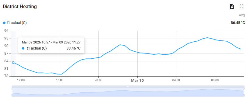
The data backend is a self-hosted Thingsboard PE instance that is accessible from the Savonia IoT network to which the Raspberry Pi is connected, and data is stored through calls to Thingsboard’s HTTP REST API using a pre-provisioned device access token. Timestamps originating from the Modbus TCP device are used in the sent data messages, so it doesn’t matter if data is read twice within the same measurement interval (this could happen with NodeJS timers and/or because of other timing inconsistencies) since the data backend doesn’t store duplicate entries. An example graph of the stored data from Thingsboard’s dashboarding UI can be seen in Figure 4.
The Conclusion
In the end, the whole integration process described in this article resulted in a working system that does what it’s supposed to. As a conclusion, it’s safe to say that the “thing works just fine”, since, at the time of writing this article, the thing has been running for 8 weeks straight without as much as a single hiccup. The amount, resolution and detail of data obtained from the district heating monitoring device is expected to turn out quite valuable in our future development of AI-based data analysis and forecasting tools addressing the optimization of public property energy consumption.
Next up in this series of articles, in “IoT Data Collection – Interfacing with Commercial Building Monitoring Solutions, Part II”, we will look into integrating multiple commercial LoRaWAN air quality monitoring devices into our data backend through the LoRaWAN gateway we deployed on the Varkaus campus during our previous sensor installation adventure.
Kirjoittajat
Mika Leskinen, RDI Specialist, DigiCenter, Savonia University of Applied Sciences, mika.leskinen@savonia.fi
Shahbaz Baig, RDI Specialist, DigiCenter, Savonia University of Applied Sciences, shahbaz.baig@savonia.fi
Laura Leppänen, RDI Specialist, Savonia University of Applied Sciences, laura.leppanen@savonia.fi
Aki Happonen, Digital Development Manager, DigiCenter, Savonia University of Applied Sciences, aki.happonen@savonia.fi
Sources
Kamstrup A/S, 2025. Data Sheet – Multical 603 and 803. Available at: https://kamstrup-delivery.sitecorecontenthub.cloud/api/public/content/59507-downloadOriginal